UNDERSTANDING TE COOLER DATASHEETS - INTRODUCTION
TEC Microsystems has about 2000 thermoelectric coolers in the standard product range. With all additional options, developed modifications and unique solutions, the total number of thermoelectric coolers in the portfolio is more than 5000. To make the optimal TEC finding easier, we provide our datasheets with a concept "one TEC - one datasheet." There is no grouping or general parametric drawings. Each datasheet has detailed and easy-to-read data about the exact thermoelectric cooler type. All TEC datasheets were updated in 2019.
TEC Microsystems TEC datasheet consists of six pages with detailed information about thermoelectric cooler dimensions, standard (default) manufacturing configuration, TEC cooling performance in various modes with related power consumption, TEC construction and additionally available manufacturing options. Below is the example of TEC Microsystems standard TEC datasheet, TEC type 1MDL06-042-09t from 1MDL06 TEC Series.
THERMOELECTRIC COOLER PERFORMANCE PARAMETERS
The Thermoelectric cooler datasheet provides information on TEC cooling performance and associated TEC current and voltage. The TEC parameters dTmax and Qmax are specified for four common environmental conditions: +27ºC in vacuum, +50ºC in dry N2, +75ºC in dry N2, and +85ºC in dry N2. TEC performance is ambient dependent and increases with ambient temperature. By default, TEC dTmax and Qmax values are specified at standard ambient modes. This is important to understand when comparing TECs from different manufacturers. TEC dTmax and Qmax parameters should be compared at the same ambient conditions. If you need to verify the performance values in application conditions other than those specified in the TEC datasheet, you can contact TEC Microsystems and get a quick response with all the necessary information.

THERMOELECTRIC COOLER DESCRIPTION AND KEY FEATURES
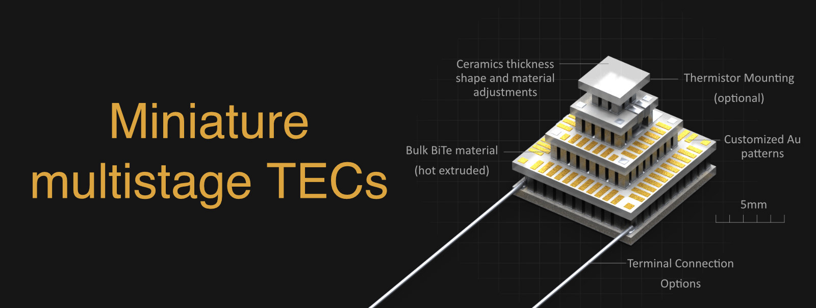
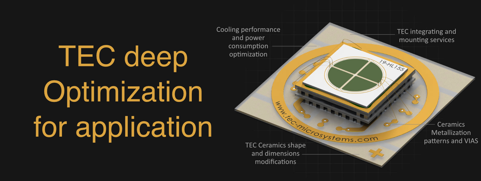
The description on the first page of the thermoelectric cooler datasheet contains key information about the TEC ceramic material, internal assembly solder, terminal wires, polarity, and some additional things related to the standard TEC configuration from the datasheet. At the same time, there is a wide range of additional customization options available if required. Thermoelectric cooler ceramic material and thickness, internal assembly solder, ceramic surfaces and terminal wires, even TEC shape - all can be modified and customized. The datasheet shows the standard manufacturing solution.
The key features section summarizes TEC assembly technology, RoHS compliance and reliability testing.
THERMOELECTRIC COOLER DIMENSIONS
TEC dimensions and tolerances on TEC Microsystems datasheets are all specified exactly for the selected TEC type, with values and tolerances available in mm and inches. The shape, proportions, and dimensions on each TEC drawing are based on the actual thermoelectric cooler as it is. You can fully rely on the TEC shape, dimensions, proportions and exterior as shown in the TEC Microsystems TEC datasheet.
If required, it's possible to adjust the height of a standard thermoelectric cooler with different ceramic thickness without affecting the TEC's performance or electrical parameters. Please refer to our FAQ, slide #43, for more details.

Note: The datasheet shows the performance parameters and standard performance plots for TEC in COOLING mode only. Estimates for heating mode (when TEC operates in reverse mode) are different and can be provided on request for specific application conditions.
THERMOELECTRIC COOLER MANUFACTURING OPTIONS
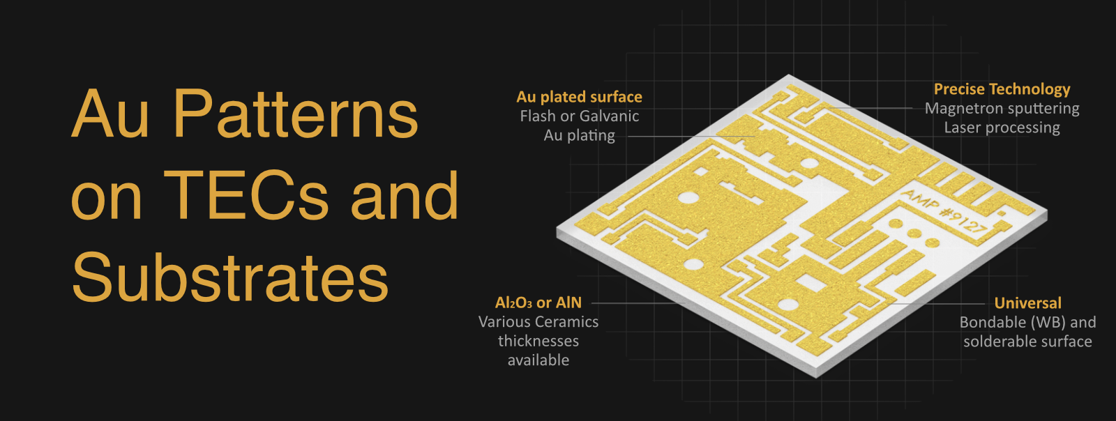
TEC Microsystems data sheets show the standard (default) manufacturing configuration and the list of available manufacturing options for each thermoelectric cooler. By default, most thermoelectric coolers are supplied with Au plated surfaces (universal for solder and adhesive mounting processes) and bare terminal wires (except for TECs with WB configuration by default). The standard list of available TEC manufacturing options is listed on page 3 of each TEC Microsystems datasheet. Special manufacturing options and additional value-added services are described in the FAQ, slides #51-59 and #80.
DATASHEETS MATERIALS COPYRIGHT
All graphics materials and data from TEC Microsystems GmbH datasheets may not be used commercially without a prior response in writing on company letterhead and signed by TEC Microsystems GmbH authority.
Thank you for respecting the intellectual property rights protected by the International Copyright laws.
All Images contain TEC Microsystems GmbH hidden watermarks for immediate proof of their origin.

TEC STANDARD PERFORMANCE PLOTS
Thermoelectric cooler performance plots are specified for four standard ambient conditions modes. In most cases, thermoelectric cooler manufacturers use +27ºC (300K) vacuum and +50ºC (323K) dry N2 conditions for TEC performance parameters in datasheets. In our case thermoelectric cooler datasheet includes two additional modes for a more detailed performance overview: +75ºC and +85ºC ambient temperatures in Dry N2 conditions. These modes are commonly used in laser and telecom applications such as transceivers and TOSAs.
The standard thermoelectric cooler performance plots are shown for five various heatloat levels on TEC, based on the percentage from TEC maximum cooling capacity (Qmax) level value. The heatload level at 0%, 20%, 40%, 60% and 80% from TEC Qmax is specified under each chart. The corresponding dT level curves are color-coded accordingly.